鑫景福致力于滿足“快速服務,零缺陷,輔助研發”PCBA訂購單需求。


PCB制造
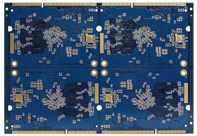
The original PCB high-frequency circuit board manufacturing process is as follows
circuit board manufacturing, circuit board design and PCBA processing manufacturers explain the original PCB high-frequency circuit board manufacturing process
1. Gerber data pre-processing
The wiring and functional characteristICs on the PCB high-frequency circuit board are designed by the customer, while the PCB high-frequency circuit board factory (high-frequency board manufacturer) is only responsible for manufacturing them, so it is the same as the communication between most designers and manufacturers. The PCB high-frequency Circuit board factory (high-frequency board manufacturer) often finds that the data designed by the customer does not conform to the process capability of the high-frequency circuit board factory, such as the line width and line spacing are too SMAll, The aperture is too small, and I can't do it. At this time, our engineer will send an EQ to communicate with you for confirmation and give corresponding suggestions.
2. PCB high-frequency circuit board negative output
Under the strict temperature and humidity control environment, the laser negative plotter is used to draw the film of the circuit board. These films are used as the image exposure of each circuit layer in the subsequent high-frequency circuit board manufacturing process, and the substrate is also used in the solder mask green oil process. In order to ensure the correctness of the relative position of each layer of line X-Y, each negative film will be drilLED with laser for the subsequent positioning of different line layers.
This kind of negative is actually a transparent PET material printed with black images, just like the film used on the projector used in our early school days.
3. Forming of inner circuit of PCB high-frequency circuit board
Multilayer circuit board refers to the inner layer structure (more than 4 layers, which includes high-frequency mixed laminate and high-frequency mixed laminate (high-frequency board manufacturer)), which usually uses a whole copper foil substrate as the material, and then every step will be acid washed to clean the copper foil surface to ensure that there is no other dust or impurities on it. As long as there is any small foreign matter, it will affect the subsequent circuit, Then, the copper foil surface will be roughened by mechanical grinding to enhance the adhesion between the dry film and the copper foil, and then a layer of dry film will be coated on the copper foil surface. Attach an inner line negative film on both sides of the copper foil substrate and mount it on the exposure machine. Use the positioning hole and vacuum suction to precisely attach the negative film to the copper foil substrate. Use ultraviolet light in the yellow light area to make the unshielded dry film on the negative film chEMIcally change and solidify on the copper foil substrate. Finally, use the developer to remove the unexposed dry film.
4. Etching of inner circuit
Etching ->Stripping
Generally, strong alkaline solution will be used to dissolve and etch the exposed copper surface, that is to say, remove the copper surface not covered by the dry film. Pay attention to the solution formula and time when etching. The thicker the copper foil, the longer the time, the wider the gap, and the wider the line. Because etching will not only corrode the exposed copper foil, but also the copper surface at the edge of the dry film will be more or less corroded. Then remove the solidified dry film originally covered on the copper foil with the film removal solution. Finally, only the circuit copper foil that should be in the design of PCB high-frequency circuit board will be left on the copper foil substrate.
5. Image positioning and target drilling
In order to accurately align the inner layer with the outer copper sheet, CCD is used to locate the preset target position on the negative film and drill the required positioning target hole. The action of shooting holes must also be performed on all the inner and outer layers of the circuit, so that the inner and outer layers of the copper foil circuit can be positioned on the same benchMARK in the subsequent process.
6. Lamination
Copper surface oxidation treatment - Plate - Pressing - Edge milling target
Generally, alkaline solvent is used to oxidize the copper surface to produce black copper oxide. The copper oxide crystals are needle like and can be used to strengthen the contact between layers. Then, the finished inner layer and the copper sheet of the outer layer of the film machine are overlapped. Here, the inner layer and the outer layer must be accurately positioned with the help of the previously drilled positioning holes, and then they are closely combined with each other through the high-temperature and high-pressure press.
7. Mechanical drilling
The main purpose of drilling is to make vias to connect the lines to be connected between layers. The through holes of multilayer circuit boards will have different conduction requirements. Here, the SIMplest 4-layer board (high-frequency composite board and high-frequency pure board) is taken as an example, so blind holes are not involved. In order to save time and improve efficiency, the drilling operation can stack three PCBs at the same time. In order to avoid the generation of burrs, aluminum plates will be paved on the top, and a backing plate will be placed below to prevent the drill from directly hitting the table. In fact, it is not necessarily that three PCB high-frequency circuit boards work together. PCB high-frequency circuit board manufacturers will determine the number of PCB high-frequency circuit boards and stacks according to PCB thickness, aperture size, hole location accuracy and other factors.
According to experience, the rotation speed of the drill, the drilling feed speed, and the life of the drill are all important factors that affect the quality of the circuit board after forming. For example, the generation of burrs will affect the subsequent electroplating quality. If the feed speed is too fast, it will cause the porosity of the glass fiber and cause the CAF phenomenon in the future.
In addition, there are laser drilling processes for boards with higher requirements. Laser can drill finer micro holes (MicroVia), but the cost is relatively high. Generally, high-density boards use laser holes, and high-frequency circuit boards (high-frequency board manufacturers) with blind holes also use laser holes.
8. Chemical copper deposition
Glue removal slag ->Chemical copper ->Electroplated copper
Because the high-speed rotation of the drill bit will produce high temperature, when the high temperature exceeds the Tg point (glass transition temperature) of the base material, glue residue will be generated. If it is not removed, the copper foil in the inner layer will not be able to form a channel through the electroplating copper, or the channel will be formed but not stable. When removing the glue residue, soak it for about 1-10 minutes with a bulking agent to allow various glue residues to expand and relax, and then remove it.
Then chemically, a thin layer of copper is applied to the wall of the non-conductive hole.
9. Outer layer lamination development
The production method and principle are the same as that of the inner lamination film development, except that there are already PTH metallization holes on the plate at this time.
10. Electroplated copper/corrosion inhibitor
Then, the copper is plated into the through-hole by electroplating until the requirements of the customer are met, generally more than 25um. Please note that the place with dry film can prevent copper plating, but other places not covered by dry film will also increase copper thickness of about 25um.
11. Etch the outer line
After the PCB high-frequency circuit board (high-frequency board manufacturer) is etched, the outer circuit has been formed, and it is the same as the designed circuit. At this time, the etching film has no need and must be removed, so as not to affect the subsequent surface treatment. The stripping of the corrosion resistance layer is usually carried out by high-pressure spraying agent.
12. Resistance welding layer
The main purpose of the solder mask is to distinguish the welding assembly area from the non welding area. In addition, it can prevent the copper layer from oxidation and meet the aesthetic requirements. It was originally thought that the solder mask layer was selectively printed. Unexpectedly, the entire PCB high-frequency circuit board was printed with solder mask paint, and then the whole PCB high-frequency circuit board was pre baked in the baking oven. Then the film was also used for contact exposure action to transfer the image on the film to the solder mask paint, and then UV was used to dry the areas not covered by the light so that the solder mask could be really attached to the circuit board, Finally, clean the area of the mask in the evolution tank to expose the copper surface that can be welded.
For simple solder mask or solder mask with large dimension tolerance, screen printed selective printing solder mask can also be used.
13. ENIG chemical nickel gold
ENIG gold deposition surface treatment process is generally to make chemical nickel deposition on copper pads, control the thickness of nickel layer by controlling the time and temperature, and then use the fresh nickel activity that has just been deposited to put the nickel pads into acidic gold water, and replace gold from the solution to the pad surface through chemical replacement reaction, that is, replace nickel, and part of the surface nickel will be dissolved in gold water. The replaced gold will gradually cover the nickel layer, until the nickel layer is completely covered, the replacement reaction will automatically stop, and the process can be completed after cleaning the dirt on the pad surface.
14. Hard gold electroplating
Electroplating hard gold belongs to selective electroplating, and its purpose is to increase its friction resistance. Therefore, in the film, it can be seen that the parts that do not need to be plated with hard gold are pasted with adhesive tape, and only the parts that need to be plated are exposed. In the film, only some PCB high-frequency circuit boards (high-frequency board manufacturers) are immersed in the electroplating solution.
15. Silk screen
Early characters (white paint) were almost completed by silk screen printing. However, the silk screen printing ink needs to add solvent and is volatile, which is harmful to human health. Now some new types of characters have been printed by inkjet printing, which is also very fast and accurate. Both silk screen printing and ink-jet printing need to go through oven fixed white paint. However, most of the doMEStic mass produced pcb high-frequency circuit boards still use screen printing technology.
At this point, the manufacturing process of PCB high-frequency circuit board (high-frequency board manufacturer) is completed, and the electrical testing, analysis and packaging are just finished later.
16. Flying needle test
The template test of PCB high-frequency circuit board usually uses the flying pin test. If the number is large, the needle bed test can also be used to save time. The test is mainly open/short circuit test
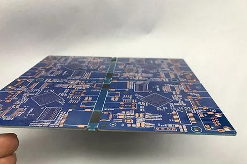
17. Forming and Splitting
For the shape forming of PCB high-frequency circuit board (high-frequency board manufacturer), the milling machine board splitter is usually used to make the shape of the circuit board and divide the boards through CNC computer control. The boards here are divided into boards according to the size of the base plate
18.V-Cut
If there is a requirement for V-Cut, the high-frequency circuit board needs to Cut out the V-slot at the defined place
19. Visual inspection, packaging and delivery
Final visual inspection and vacuum packaging for shipment
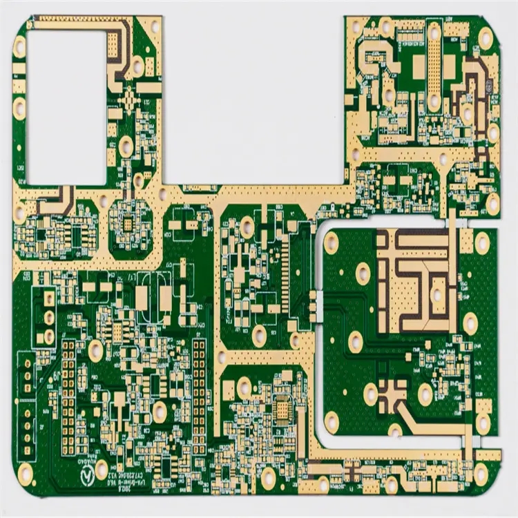
PCB manufacturing, PCB design and PCBA processing manufacturers explain the original PCB high-frequency PCB manufacturing process.


抖音二維碼

Q Q二維碼

微信二維碼
點擊
然后
聯系
然后
聯系
電話熱線
13410863085Q Q

微信

- 郵箱