鑫景福致力于滿足“快速服務(wù),零缺陷,輔助研發(fā)”PCBA訂購單需求。


PCB制造
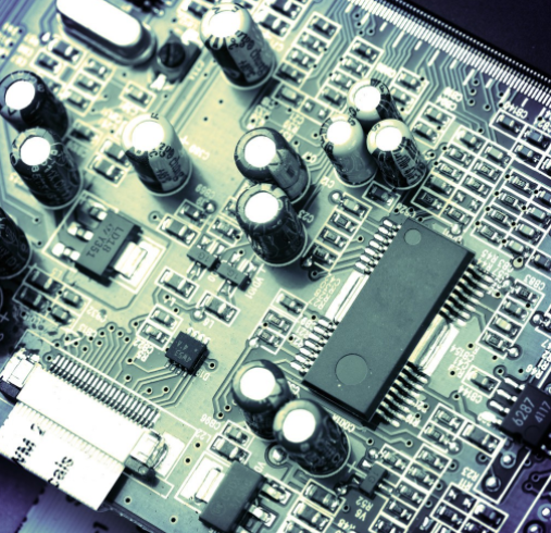
Best practICe technology for high-speed PCB wiring
This circuit board design also requires extra effort in the layout of high-speed circuits Sensitive networks must be routed according to specific high-speed rules and many other high-speed design requirements that must be followed These include everything from schematic organization to component placement When discussing high-speed routing technology, we will study all these technologies to help you complete the next task PCB design
Previous high-speed design considerations PCB layout
Compared with the circuit boards used on standard circuit boards, the successful connection of high-speed circuits requires more preparation. While balancing the conventional manufacturing and assembly requirements of circuit boards, signal paths, controlLED impedance wiring and electromagnetic interference must be considered in high-speed design. Preparation must begin before the layout starts to keep all these requirements in order:
Schematic: To help you with high-speed cabling, the first thing you can do is start with a clean schematic. During PCB layout, there should be a high-speed circuit logic flow that is easy to follow. Any instructions should also be communicated to the layout personnel to avoid any confusion in the future.
Circuit board

Layer stacking: High speed cabling usually requires stripline or microstrip layer configuration. This provides a mask layer for sensitive track routing, which helps prevent electromagnetic interference problems and maintain the signal integrity of the circuit. Before starting the layout, you should reach an agreement on stacking with the PCB contract manufacturer to provide you with a working basis and ensure the manufacturability of the circuit board.
Design rules: In addition to the standard track width and spacing rules, there will also be a new set of high-speed design rules and constraints. These will include routing rules for specific network types, differential pairs, track lengths and topologies, and impedance control. There may also be specific requirements for blind holes, embedded through-holes, micro through-holes and other high-speed restrictions.
After selecting these items from the to-do list, you can start PCB layout.
Layout and Wiring Technology in High Speed PCB Design
Although there are many high-speed cabling technologies that need to be discussed, the first topic to be discussed is component placement. Good wiring starts with good component layout, regardless of whether the circuit board is designed for high speed.
Component placement
Use the standard component placement method, starting with connectors, large CPUs, and memory devices. In order to obtain the best signal path while continuing to place parts, please follow the logic flow of the schematic diagram. Many more important CPU and memory devices will need a large number of bypass capacitors. Please place them immediately, or there may not be enough space for them in the future. When placing, remember to reserve space for routing channels and vias throughout the board stack. In addition to the high speed requirements, remember that your placement still needs to comply with the Design for Manufacturability (DFM) rules and take into account the heat dissipation requirements of the heating components.
Escape route
You are now ready to route, but you need to create escape routes for all fine pitch equipment before you begin laying the tracks. If you are processing a large part, such as a BGA packet containing hundreds or thousands of pins, you can access each pin for routing. This accessibility is usually achieved by routing diagonally from the external pin to the through hole.
For the next row of pins, a very short trace is usually used to connect to the through-hole between BGA pads, which is called dog bone pattern. However, if the BGA pin spacing is too SMAll, it may be necessary to use vias, micro vias or both in pad technology, but the manufacturer's approval of these PCB technologies must be obtained first. Here is a useful tip. Component manufacturers usually provide recommended wiring modes for their parts. Please check this to save some time.
Trace Route
After completing the escape route, it is time to select the route for the remaining circuit boards. If the design rules are fully set, you can manually complete this routing using the automatic interactive routing tool or the batch processing routing tool. Regardless of the method used, the following points should be kept in mind to ensure successful cabling:
The high-speed signal path must be kept short and routed from point to point.
Sensitive traces shall be routed on the inner layer sandwiched between the reference planes in the stripline configuration.
The differential pair must be wired in pairs. Use the automation features of the design system to route these tracks and ensure that these pairs are not interrupted by vias or other obstacles.
For network groups whose lengths must all match, start with the longest connection. For the remaining networks in the group, an adjustment function is added to each track to match the first network routed to the same length. Tuning is usually done automatically by adding waveform or trombone topology to the track.
Do not arrange sensitive digital circuits through noisy power supplies or analog areas of circuits.
Power supply and ground plane
Designing a clean distribution network (PDN) for high-Speed PCBs is critical to the overall success of the design. High speed components generate more noise on the circuit board due to their switching speed, which is controlled by the bypass capacitor. It is also important to remember that the ground plane will be used as the reference plane for signal return. Be careful not to route sensitive traces where these signal return paths are blocked by dense through-hole placement, circuit board cutting or splitting planes, as this will reduce the signal integrity of these traces.
As you can see, high-speed wiring is more than just laying some unique lines on a circuit board. Many aspects of PCB layout must be completed through wiring to complete high-speed design. As we said at the beginning, before the layout starts, we must first contract with the PCB manufacturer to set the circuit board correctly.
Cooperate with PCB CM to obtain the best high-speed wiring technology
Although PCB design may generally become old and work by converting layer stacks to layouts, high-speed design should start with a clearly configured stack Although PCB designers are usually familiar with different circuit board configurations, high-speed design needs to consider many other variables It includes circuit board data, controlled impedance wiring, layer pairs, and assembly processes The best thing you can do is consult your PCB contract manufacturer. First, make sure that your design uses the optimal layer configuration
PCB Design Tutorial What is a PCB?
11-13,2022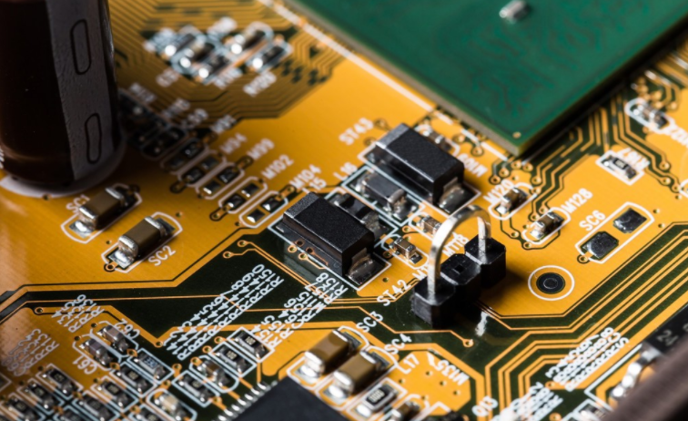


抖音二維碼

Q Q二維碼

微信二維碼
點(diǎn)擊
然后
聯(lián)系
然后
聯(lián)系
電話熱線
13410863085Q Q

微信

- 郵箱