鑫景福致力于滿足“快速服務(wù),零缺陷,輔助研發(fā)”PCBA訂購單需求。


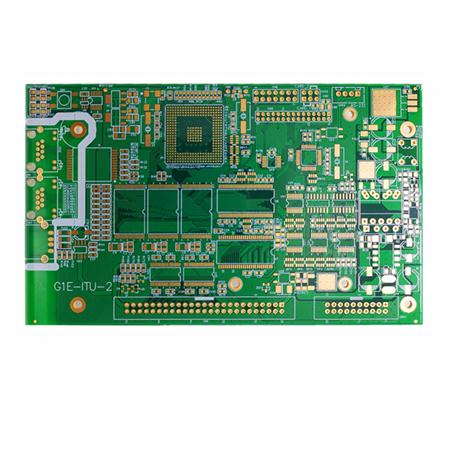
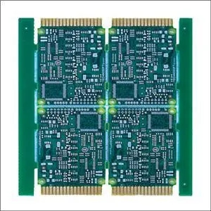
PCB制造
It is time to pay attention to some details in PCB testing to ensure product quality. When testing PCB, we should pay attention to the following nine common sense.

1. It is strICtly forbidden to use grounded test equipment to contact live TV, audio, video and other equipment on the bottom plate to detect PCB board without isolation transformer
It is strictly prohibited to directly test TV, audio, video and other equipment without power isolation transformer with grounded shell. Although general radio recorders have power transformers, when touching special TV or audio equipment, especially those with large output power or little understanding of the nature of the power used, it is necessary to first find out whether the chassis of the recorder is charged, otherwise it is very easy to cause power short circuit with TV, audio and other equipment charged on the backplane, affecting the integrated circuit, causing further expansion of the fault.
2. Pay attention to the insulation property of electric soldering iron when testing PCB board
It is not allowed to use soldering iron for welding with electricity. Make sure that the soldering iron is not charged. It is better to ground the shell of the soldering iron. Be more careful with MOS circuits. It is safer to use 6-8V low-voltage circuit iron.
3. Understand the working principles of integrated circuits and related circuits before testing PCB boards
Before checking and repairing the integrated circuit, it is necessary to be familiar with the function, internal circuit, main electrical parameters, the role of each pin, the normal voltage of the pin, the working principle of the circuit composed of the waveform and peripheral components. If the above conditions are met, the analysis and inspection will be much easier.
4. Test PCB board to avoid short circuit between pins
When measuring the voltage or testing the waveform with the oscilloscope probe, the probe or probe shall not cause short circuit between the pins of the integrated circuit due to sliding, and it is better to measure on the peripheral printed circuit directly connected with the pins. Any transient short circuit is easy to damage the integrated circuit, so you should be more careful when testing CMOS integrated circuits in flat package.
5. The internal resistance of the PCB board testing instrument is large
When measuring DC voltage of integrated circuit pins, a multimeter with internal resistance greater than 20K Ω/V shall be selected, otherwise there will be large measurement error for some pin voltages.
6. Pay attention to heat dissipation of power integrated circuit when detecting PCB
The power integrated circuit shall have good heat dissipation, and it is not allowed to work in a high-power state without a radiator.
7. The lead wire of PCB board shall be tested reasonably
If it is necessary to add peripheral components to replace the damaged parts inside the integrated circuit, SMAll components shall be selected, and the wiring shall be reasonable to avoid unnecessary parasitic coupling, especially the grounding terminal between the audio power amplifier integrated circuit and the preamplifier circuit.
8. Ensure the welding quality when testing PCB boards
When welding, it is sure to weld firmly, and the accumulation and porosity of solder are easy to cause false soldering. The welding time is generally no more than 3 seconds, and the power of the soldering iron should be about 25W of internal heating type. The soldered integrated circuit should be carefully checked. It is better to use an ohmmeter to measure whether there is a short circuit between the pins, and then turn on the power after confirming that there is no solder adhesion.
9. Do not judge the damage of integrated circuit easily when detecting PCB board
Do not easily judge whether the integrated circuit is damaged. Because the vast majority of integrated circuits are directly coupLED, once a circuit is abnormal, it may lead to multiple voltage changes, which may not be caused by the damage of the integrated circuit. In addition, in some cases, when the measured voltage of each pin is consistent with or close to the normal value, it does not necessarily mean that the integrated circuit is good. Because some soft faults will not cause changes in DC voltage.
PCB board debugging method
For the new PCB just brought back, we should first roughly observe whether there are problems on the board, such as obvious cracks, short circuits, open circuits, etc. If necessary, check whether the resistance between the power supply and the ground wire is large enough.
For a newly designed circuit board, debugging often meets some difficulties, especially when the board is relatively large and there are many components. But if we master a set of reasonable debugging methods, we will get twice the result with half the effort.
PCB board debugging steps
1. For the new PCB just brought back, we should first roughly observe whether there are problems on the board, such as obvious cracks, short circuits, open circuits, etc. If necessary, check whether the resistance between the power supply and the ground wire is large enough.
2. Then there is the installation of components. If you are not sure to ensure the normal operation of independent modules, you'd better not install them all, but part by part (for small circuits, you can install them all at once), so that it is easy to determine the fault range and avoid having no way to start when encountering problems.
Generally speaking, the power supply part can be installed first, and then power on to detect whether the power supply output voltage is normal. If you are not sure when powering on (even if you are sure, you are also recommended to add a fuse, just in case), you can consider using an adjustable regulated power supply with current limiting function.
Preset the overcurrent protection current, then slowly increase the voltage of the stabilized voltage power supply, and monitor the input current, input voltage and output voltage. If there are no over-current protection problems during the upward adjustment and the output voltage is normal, the power supply is OK. Otherwise, disconnect the power supply, find the fault point, and repeat the above steps until the power supply is normal.
3. Next, gradually install other modules. After each module is installed, power on and test it. Follow the above steps when powering on to avoid burning components due to overcurrent caused by design errors or/and installation errors.
Methods for Finding Faulty PCB Boards
1. Measuring Voltage Method for Finding Faulty PCB Boards
First, check whether the voltage of each chip power pin is normal, then check whether the reference voltage is normal, and whether the working voltage of each point is normal. For example, when the general silicon triode is turned on, the BE junction voltage is about 0.7V, while the CE junction voltage is about 0.3V or less. If the BE junction voltage of a triode is greater than 0.7V (except for special triodes, such as Darlington transistors), the BE junction may be open.
2. Signal injection method for finding fault PCB
Add the signal source to the input terminal, and then measure the waveform of each point backward in order to see if it is normal, so as to find the fault point. SometiMES we also use SIMpler methods, such as holding a pair of tweezers to touch the input terminals at all levels to see if the output terminals react, which is often used in audio, video and other amplification circuits (but it should be noted that this method cannot be used for circuits with hot backplane or circuits with high voltage, otherwise it may lead to electric shock). If there is no reaction at the level before the collision, but there is reaction at the level after the collision, it indicates that the problem is at the level before the collision, and the inspection shall be focused.
3. Other methods for finding faulty PCB boards
There are many other ways to find the fault point, such as looking, listening, SMElling, touching, etc.
"Look" is to see if the components have obvious mechanical damage, such as crack, burning black, deformation, etc;
"Listening" is to listen to whether the working sound is normal, for example, something that should not be loud is ringing, the place that should be loud is silent or the sound is abnormal;
"Smell" means to check whether there is any smell, such as the smell of burning, the smell of capacitor electrolyte, etc. An experienced electronic maintenance personnel is very sensitive to these smells;
"Touch" means to test whether the temperature of the device is normal, such as too hot or too cold.
Some power devices will generate heat when they work. If they feel cold, it can basically be judged that they are not working. However, if the place that should not be hot is hot or the place that should be hot is too hot, it is not good. General power triodes, voltage stabilizing chips, etc., can work under 70 degrees. What is the concept of 70 degrees? If you press your hand on it for more than three seconds, it means that the temperature is below 70 degrees (please try to touch it first, and don't burn your hand).


抖音二維碼

Q Q二維碼

微信二維碼
點擊
然后
聯(lián)系
然后
聯(lián)系
電話熱線
13410863085Q Q

微信

- 郵箱