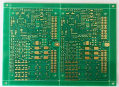
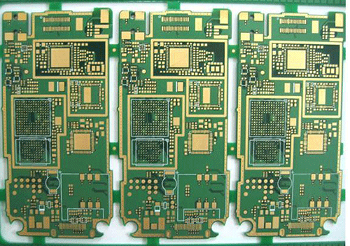
鑫景福致力于滿足“快速服務,零缺陷,輔助研發”PCBA訂購單需求。


PCBA方案設計
Abstract: In electronIC circuits, common impedance interference has a great impact on the normal operation of the circuit. In PCB circuit design, especially in high-frequency circuit PCB design, the influence of common impedance of ground wire must be prevented. By analyzing the form of common impedance interference, this paper introduces in detail the restraining effect of one point grounding on common impedance interference in electronic circuits, especially in high-frequency circuits, and the problems that should be paid attention to when using one point grounding to prevent common impedance interference.
At the same time, the main forms and requirements of ground wire layout in PCB board are briefly described
In the electronic circuit, most components form a loop through the ground wire. Whether the line design is reasonable or not directly affects the work of the circuit. Minimize the interference to signal transmission caused by improper ground wire design.
In the circuit diagram, grounding is usually represented by symbols, representing the zero potential in the circuit, and is used as the common reference point of other points of the circuit. The voltage, current and signal level of each point of the circuit are expressed by the ground wire as the reference voltage. When reading the circuit diagram and understanding the working state of the circuit, the ground wire and each grounding point are often regarded as zero potential points without potential difference. In the actual circuit work, due to the existence of the impedance (resistance, inductance) of the ground wire, a certain potential difference will be generated. The existence of these potential differences will inevitably affect the work of the circuit. In PCB design, we must pay attention to and eliminate the influence of ground wire impedance.
1. The form of ground wire interference to the circuit
1.1 Full current common impedance interference
, circuit 1 and circuit 2 form a loop with the power supply through the common ground wire AB. Section AB can be equivalent to a series circuit of resistance and inductance, thus forming a common impedance effect. During operation, the current variation of circuit 1 and circuit 2 will cause the potential change of point A, which will cause circuit 1 and circuit 2 to interfere with each other. If circuit 2 outputs to circuit 3, the interference will also enter circuit 3, thus forming a full current common impedance interference.
For example, there is a section of printed wire with a length of 10cm and a width of 1.5cm, its copper foil thickness is 50 microns, and the wire resistance is:
if ρ= 0. 02, then R is about 0. 026 Ω. When circuit 1 works at low frequency, the alternating current of the circuit is 1A, and about 0.026V alternating voltage drop is generated on this section of printed wire and acts on circuit 2. At high frequency, the common impedance interference of the ground wire is mainly the inductance of the conductor. When the length of a section of conductor is far greater than its width, the self inductance of the conductor can be calculated as 0.8 μ g/m. When the working frequency of the same 10cm long conductor passing through is 30MHz, the inductance of this section of conductor is RL=2 π L ≈ 16 Ω. It can be seen that when the frequency increases, the inductive reactance of the wire will be several orders of magnitude greater than the resistance of the wire itself. Even if a SMAll high-frequency current flows through the wire, such as 10mA, a 0.16V high-frequency voltage will be generated on the wire. Therefore, for high-frequency circuit, when making PCB, the printed PCB wire should be as short as possible to reduce the loss and interference caused by the wire inductance to the circuit.
1.2 Local current common impedance interference
When the printed board adopts ring ground wire, each grounding element shall be grounded in a decentralized manner nearby. In this way, part of the AC signal of the last stage forms a loop through the ground wire AD, which generates AC voltage drop on the conductor AD.
Since the EMItter and base of the front stage transistor share the same conductor BC with the last stage, common impedance interference is generated on the conductor BC. This interference is coupLED on the common ground wire in the form of local current, forming local current common impedance interference.
The total current common impedance interference mainly exists between stages. Local current common impedance interference refers to the interference to other circuits caused by poor grounding points of some or individual components and wires.
2. Methods to prevent common impedance interference
Internal grounding at all levels. Internal grounding at all levels is the main method to prevent local current common impedance interference. That is, it effectively prevents the AC signal of the current level from escaping into the circuit outside the current level through each grounding element, or the AC signal of other circuits from being detected through each grounding element of the current level.
Whether for low frequency, intermediate frequency or high frequency circuits, the only effective way to prevent the common impedance interference of local current is to use one point grounding.
The grounding elements inside each level, that is, all the grounding elements of the emitter base and collector of the current level circuit, are arranged to be connected to the ground wire at one grounding point.
In this way, it can effectively prevent the transmission and reception of AC signals through the grounding elements, making the grounding pure.
In the actual circuit, there are many grounding elements at all levels, so it is impossible to thread these elements into a threading hole at the same time. Instead, the grounding elements at this level are arranged as close as possible in a section or an area of the common ground wire, as shown in Figure 4a. SometiMES, due to the volume limitation or arrangement of components, when it is difficult to arrange nearby, the grounding form can be adopted, which can also achieve the effect of one point grounding.
3 Matters needing attention in one point grounding
3.1 Scope of grounding elements at this level
The scope of the grounding element at this level refers to the element directly connected to the transistor at this level or coupled through capacitance. Inductively coupled secondary and PCB components do not belong to this level
3.2 Use grounding branch as one point grounding
When there are few components and small volume, the one point grounding layout is easy to handle; Long grounding branches can be used when there are many components and the volume is large. In typesetting, it can also be arranged around the printing plate, but components of other levels should not be connected to this grounding branch, and the far end of the grounding branch should not be connected to other ground wires.
3.3 One point grounding also includes components outside the board of this level
One point grounding includes not only the components inside the board of the current level, but also the components outside the board that are directly or through capacitance coupling with the current level. This point is often ignored in PCB design, resulting in common impedance interference of local current.
3.4 One point grounding of high frequency circuit
The ground wire of high-frequency circuit generally adopts large area covering grounding, but this does not mean that the grounding of internal components at all levels can be decentralized.
4 Layout of PCB ground wire in the board
The ground wire in the printed board is used to connect the grounding between all levels or parts of the circuit. The layout of ground wires in the board shall mainly prevent the full current common impedance interference between all levels and parts.
4.1 Requirements for layout of ground wires in the board
When there are many circuits in the board, the layout of ground wires must meet the following requirements:
The ground wires of each part must be separated.
In order to eliminate or minimize the common ground line segment of each part, the lead out point of the main ground wire must be reasonable.
To prevent common impedance interference caused by all parts passing through the common outgoing line of the general ground wire, the ground wire of some parts of the circuit can be led out separately when necessary.
4.2 Layout form of ground wire in the board
Parallel shunt grounding mode is adopted. The floor of the board is at the lower right corner of the printed board. For the general ground lead out point in the board, it shall be uniformly considered according to the layout of the ground wire in the board. The general ground shall be selected at the point close to the ground wire of each part as far as possible, and the ground wire between the general ground and the power supply shall also be short.
In digital circuits, because a large number of flip-flop and gate circuits are very sensitive to interference signals, each circuit will produce certain pulse interference when it is in the switching state, causing false triggering of flip-flop and gate circuits. This will directly affect the stability of the circuit, which can be designed according to the level, the working state or one integrated block.
Bus bar type: the bus bar is a strip symmetrical transmission line. The DC resistance decreases due to the increase of its thickness and width. More importantly, this symmetrical transmission mode has better low impedance characteristics than single line transmission, and overcomes the influence of inductance component on PCB circuit during single line transmission.
Large area coverage grounding: in the digital circuit with high working frequency and high-speed switch, the grounding wire cannot adopt strip distribution, and the grounding mode with large area coverage should be adopted.
When there are many conductors in the board, double-sided printed boards are used to avoid the grounding effect being affected by the disconnection of conductors. One side is used for grounding. Large area grounding shall be adopted to prevent common impedance interference caused by local current coupling of grounding PCB components. Therefore, the Layout of components at all levels shall be centered on the transistors and integrated blocks at the same level as far as possible, and the components shall be centralized by level, and the grounding area shall be set at the center of the components at the same level.


抖音二維碼

Q Q二維碼

微信二維碼
點擊
然后
聯系
然后
聯系
電話熱線
13410863085Q Q

微信

- 郵箱