鑫景福致力于滿足“快速服務(wù),零缺陷,輔助研發(fā)”PCBA訂購(gòu)單需求。


PCBA方案設(shè)計(jì)
Introduction to PCB board anti-interference and PCB board pad knowLEDge
For electronIC systems with microprocessors, anti-interference and electromagnetic compatibility must be considered in the design process, especially for systems with high clock frequency and fast bus cycle; System with high-power and large current drive circuit; A system with weak analog signal and high-precision A/D converter. The following measures shall be taken to increase the system's ability to resist electromagnetic interference:
1) Select microprocessor with low clock frequency
As long as the controller performance can meet the requirements, the lower the clock frequency is, the better. A low clock can effectively reduce noise and improve the anti-interference ability of the system. Because square wave contains various frequency components, its high-frequency components can easily become noise sources. Generally, high-frequency noise with a frequency of 3 tiMES the clock frequency is the most dangerous.
2) Reduce distortion in signal transmission
When high-speed signal (signal with high frequency=signal with fast rising edge and falling edge) is transmitted on the copper film line, due to the influence of inductance and capacitance of the copper film line, the signal will be distorted. When the distortion is too large, the system will not work reliably. As a general requirement, the shorter the copper film wire for signal transmission on PCB, the better, and the fewer the vias, the better. Typical value: the length shall not exceed 25cm, and the number of vias shall not exceed 2.
3) Reduce cross interference between signals
When a signal line has a pulse signal, it will interfere with another weak signal line with high input impedance. At this time, the weak signal line needs to be isolated by adding a grounded contour line to enclose the weak signal, or increasing the distance between lines. For interference between different layers, the method of adding power and ground layers can be used to solve the problem.
4) Reduce noise from power supply
While the power supply provides energy for the system, it also adds its noise to the power supply system. Reset, interrupt and other control signals in the system are most vulnerable to interference from external noise. Therefore, capacitors should be appropriately added to filter out these noises from the power supply.
5) Pay attention to the high-frequency characteristics of PCB boards and components
In the case of high frequency, the distributed inductance and capacitance of copper film wires, pads, vias, resistors, capacitors, and connectors on a PCB cannot be ignored. Due to the influence of these distributed inductors and capacitors, when the length of copper film wire is 1/20 of the wavelength of signal or noise, antenna effect will be generated, which will generate electromagnetic interference internally and EMIt electromagnetic waves externally. In general, vias and pads will generate 0.6pF capacitance, an integrated circuit package will generate 2-6pF capacitance, a PCB connector will generate 520mH inductance, and a DIP-24 socket will have 18nH inductance. These capacitors and inductances have no impact on circuits with low clock frequency, while circuits with high clock frequency must be paid attention to.
6) Element layout shall be reasonably divided
Anti electromagnetic interference shall be fully considered for the position of components arranged on the circuit board. One of the principles is that the copper film wires between various components should be as short as possible. In terms of layout, analog circuits, digital circuits and circuits (relays, large current switches, etc.) that generate large noise should be reasonably separated to minimize the signal coupling between them.
7) Properly handle the ground wire
The ground wire shall be treated according to the single point grounding or multi-point grounding mentioned above. Connect analog ground, digital ground and high-power device ground separately, and then converge to the grounding point of the power supply. The leads outside the PCB board shall be shielded wires. For high-frequency and digital signals, both ends of the shielded cables shall be grounded. For low-frequency analog signals, the shielded wires are generally grounded at a single end. The circuit which is very sensitive to noise and interference or the circuit with high frequency noise especially serious shall be shielded with metal shield.
8) Decoupling capacitor
The high frequency characteristics of ceramIC chip capacitor or multilayer ceramic capacitor are better. When designing PCB board, a decoupling capacitor shall be added between the power supply and ground wire of each integrated circuit. The decoupling capacitor has two functions: on the one hand, it is the energy storage capacitor of the integrated circuit to provide and absorb the charging and discharging energy at the moment of opening and closing the door of the integrated circuit; on the other hand, it bypasses the high-frequency noise generated by the device. Typical decoupling capacitance in digital circuit is 0.1 μ F. Such capacitors have a 5nH distributed inductance, which can have a good decoupling effect on noise below 10MHz. In general, select 0.01~0.1 μ The capacitance of F is OK.
It is generally required to add a 10 for every 10 integrated circuits μ F charging and discharging capacitance. In addition, a 10~100 should be bridged at the power terminal, four corners of the circuit board, etc μ F capacitance.
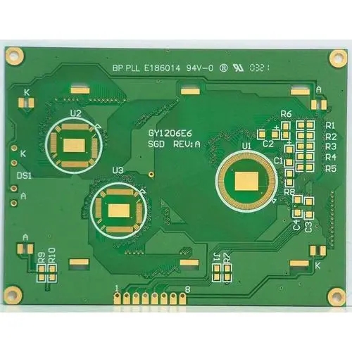
Pad size: The inner hole size of the pad must be considered from the component lead diameter and tolerance size, as well as the thickness of the tin coating, hole diameter tolerance, hole metallization plating thickness, etc. Generally, the metal pin diameter plus 0.2mm is taken as the inner hole diameter of the pad. For example, if the diameter of the metal pin of the resistance is 0.5mm, the diameter of the pad hole is 0.7mm, and the outer diameter of the pad should be the pad hole diameter plus 1.2mm, and the minimum should be the pad hole diameter plus 1.0mm. When the pad diameter is 1.5mm, the square pad can be used to increase the peel strength of the pad. For pads with hole diameter less than 0.4mm, pad outer diameter/pad hole diameter=0.5~3. For pads with hole diameter greater than 2mm, pad outer diameter/pad hole diameter=1.5~2.
Common pad size:
Diameter of pad hole/mm
0.4; 0.5; 0.6; 0.8; 1.0; 1.2; 1.6; two
Outer diameter of pad/mm
1.5; 1.5; 2.0; 2.0; 2.5; 3.0; 3.5; four
Precautions for pad design are as follows:
1) The distance from the edge of the pad hole to the edge of the PCB board shall be greater than 1mm, so as to avoid pad defects during processing.
2) When the copper film line connected to the pad is thin, the connection between the pad and the copper film line should be designed as a teardrop, so that the pad can not be easily stripped, and the connection between the copper film line and the pad can not be easily disconnected.
3) Adjacent pads shall be free from sharp corners.
PCB manufacturers, PCB designers and PCBA manufacturers will explain PCB anti-interference and PCB pad knowledge to you.


抖音二維碼

Q Q二維碼

微信二維碼
點(diǎn)擊
然后
聯(lián)系
然后
聯(lián)系
電話熱線
13410863085Q Q

微信

- 郵箱