鑫景福致力于滿足“快速服務(wù),零缺陷,輔助研發(fā)”PCBA訂購單需求。


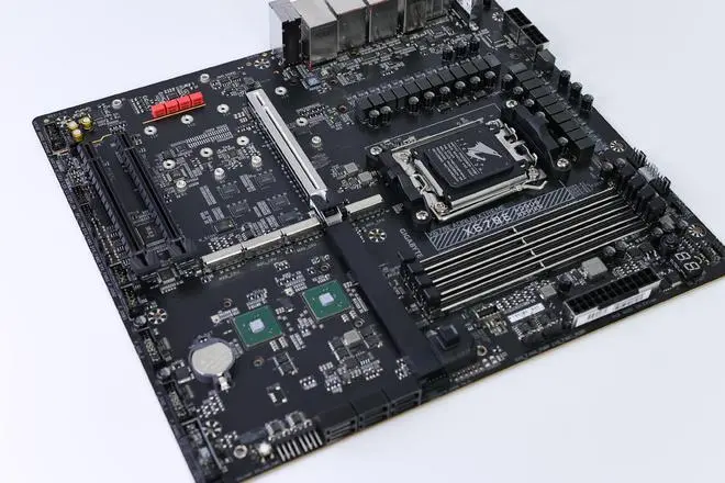
PCBA方案設(shè)計
The packaging of PCB parts can be specified in the circuit diagram or when the network table is introduced. When designing a circuit diagram, you can specify it in the Footprint setting item in the part attribute dialog box, or you can specify part encapsulation when importing a network table.
Question 1: What is a part package and what is the difference between it and a part?
Answer: (1) Part packaging refers to the appearance and solder joint position indICated when the actual part is welded to the circuit board.
(2) Part packaging is just the appearance and solder joint position of the part, while pure part packaging is just a concept of space, so different parts can share the same part packaging; On the other hand, the same kind of parts can also have different packages. For example, RES2 represents resistance, and its package forms include AXAIL0.4, AXAIL0.3, AXAIL0.6, etc. So when taking welded parts, you should know not only the part name but also the part package.
(3) The packaging of parts can be specified when designing the circuit diagram or when introducing the network table. When designing a circuit diagram, you can specify it in the Footprint setting item in the part attribute dialog box, or you can specify part encapsulation when importing a network table.
Question 2: What are the differences between wires, flying wires and networks?
Answer: The wire, also known as copper film wiring, is used to connect various solder joints. It is the most important part of the printed circuit board. PCB design focuses on how to arrange the wire. Another kind of wire related to the wire is often calLED flying wire, also called pre stay wire. The flying wire is a kind of connection generated by the system according to rules after the introduction of the network table to guide the wiring. There is an essential difference between flying wire and conductor. The flying wire is only a formal connection, which only formally represents the connection relationship between the various welding points, and has no electrical connection significance. The wires are arranged according to the connection relationship between the solder joints indicated by the flying wire, which is a connection line with electrical connection significance. The network is different from the wire. The network also includes PCB solder joints. Therefore, when referring to the network, not only the guide line but also the solder joints connected to the wire are included.
Q3: What is the difference between the inner layer and the middle layer?
A: The middle layer and the inner layer are two concepts that are easily confused. The middle layer refers to the middle plate layer used for wiring, in which wires are laid; The inner layer refers to the power supply layer or ground wire layer, which is generally composed of a whole piece of copper film without wiring.
Q4: What are internal network tables and external network tables, and what are the differences between them?
Answer: There are external network tables and internal network tables. External network table refers to the imported network table, that is, the schematic network table generated by Sch or other schematIC design software; The internal network table is a modified network table used for wiring inside the PCB system according to the imported external network table. Strictly speaking, these two kinds of network tables are completely different concepts, but readers need not strictly distinguish between them.
Q5: What is the role of Network Table Manager?
Answer: First, introduce the network table. The introduction process of this network table is actually the process of loading the schematic design data to the PCB of the PCB design system. All data changes in PCB design system can be completed through Netlist Macro. The system automatically generates network macro by comparing and analyzing network table files and internal data of PCB system. Second, the network table manager can be used to directly edit the connection relationship between various components of the circuit board in the PCB system to form a network table.
Question 6: What are classes and what are the advantages of introducing the concept of classes?
A: A class is a collection of units with the same meaning. Class definition in PCB is open to users, who can define the meaning and composition of classes themselves. The introduction of classes in PCB has two main functions: (1) It is convenient for wiring. F In the wiring process of the circuit board, some networks need special processing, such as some important data lines. In order to avoid interference from other components on the circuit board, it is often necessary to increase the safety distance between these data lines and other components during PCB wiring. These data lines can be grouped into one class. When setting automatic routing safety spacing rules, this class can be added to the rules, and the safety spacing can be appropriately increased, so that the safety spacing of all data lines in this class will be increased during automatic routing; In the wiring process of the circuit board, the power supply and ground wire often need to be thickened to ensure the reliability of the connection. The power supply and ground wire can be classified into one category. When setting the width constraint rule, this category can be added to the rule, and the wire width can be appropriately increased, so that the power supply and ground wire in this category will become wider during automatic PCB wiring. (2) Easy to manage circuit board components F For a large circuit board, there are many parts packaged on it, and thousands of networks, which are very MESsy. Classes can be used to manage circuit boards easily. For example, classify all the input networks in the circuit board. When looking for an input network, just search in this input network class; You can also classify all the voltage limiting resistors in the circuit board. When looking for a voltage limiting resistor, you only need to look for it in this voltage limiting resistor class.
Question 7: How to add additional solder joints to the network
Answer: First add PCB solder joints to the circuit board, and then double-click the solder joints to open the solder joint attribute setting dialog box. Select the appropriate network in the Net item in Advaced to complete the placement of solder joints.
Q8: What is the use of inner layer segmentation?
Answer: The separated inner layer can be used to connect some important circuits, which can improve the anti-interference ability and also protect important circuits.
Q9: What is the role of copper coating and what should be paid attention to?
Answer: The main function of copper coating is to improve the anti-interference capability of the circuit board. If the line needs to be wrapped with conductors or filled with tears, the copper coating should be carried out at the end


抖音二維碼

Q Q二維碼

微信二維碼
點擊
然后
聯(lián)系
然后
聯(lián)系
電話熱線
13410863085Q Q

微信

- 郵箱