鑫景福致力于滿足“快速服務(wù),零缺陷,輔助研發(fā)”P(pán)CBA訂購(gòu)單需求。


PCBA加工
Improving Tin Permeability and the Role of chip Capacitors in PCB
Process for Improving Tin Permeability in PCBA Production
Regarding PCBA tin penetration, we should know the following two points:
1. PCBA tin penetration requirements
According to IPC standards, PCBA tin penetration requirements for through-hole solder joints are generally greater than 75%. In other words, the tin penetration standard used for visual inspection of panel surface shall not be less than 75% of the hole height (plate thICkness). The tin permeability of PCBA should be 75% - 100%. The electroplated through-hole is connected to the heat dissipation layer or heat conduction layer for heat dissipation, and the PCBA tin penetration requirement is greater than 50%.
2. Factors Affecting the Penetration of PCBA Tin
The poor tin permeability of PCBA is mainly affected by data, wave soldering process, flux and manual soldering.
Specific analysis of influencing factors PCBA tin penetration:
1. Information
Tin melted at high temperature has strong permeability, but not all metals to be welded (PCB boards, components) can penetrate, such as aluminum, whose surface usually forms a dense protective layer automatically, while the difference in internal molecular structure makes it difficult for other molecules to penetrate. Second, if there is an oxide layer on the metal surface to be welded, it will also block the penetration of molecules. We usually use flux treatment or wipe with gauze.
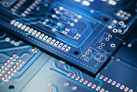
Circuit board

2. Wave soldering process
PCBA tin penetration is directly related to wave soldering process. Re optimize the welding parameters with poor tin penetration, such as wave height, temperature, welding time or moving speed. First, reduce the rail angle appropriately and increase the wave crest height to increase the contact amount between liquid tin and the welding end; Then, increase the wave soldering temperature. In general, the higher the temperature, the stronger the permeability of tin, but this should be considered. Parts can withstand temperature; Finally, it can reduce the speed of the conveyor belt, increase preheating and welding time, enable the flux to completely remove oxides, penetrate into the welding end, and increase the consumption of tin.
3. Flux
Flux is also an important factor affecting the poor permeability of PCBA tin. Flux is mainly used to remove oxides on PCB and component surfaces and prevent reoxidation during welding. Poor selection of flux, uneven coating and too SMAll amount. This will result in poor tin penetration. You can choose a well-known brand of flux, which will have higher activation and wetting effects, and can effectively remove oxides that are difficult to remove; Check the flux nozzle. The damaged nozzle needs to be replaced in time to ensure that the PCB surface is coated with an appropriate amount of flux. Give full play to the flux effect of flux.
4. Manual welding
In the actual plug-in welding quality inspection, the solder surface of a considerable number of weldments has only one taper, and there is no tin penetration in the through-hole. Functional testing confirms that many of these parts are welded. This situation is more common in manual parts. In the welding process, the reason is that the temperature of the soldering iron is inappropriate and the welding time is too short. Poor permeability of PCBA tin easily leads to false welding problems and new rework costs. If the requirements for PCBA tin permeability are relatively high and the welding quality requirements are relatively strict, then selective wave soldering can be used, which can effectively reduce the problem of poor PCBA tin permeability.
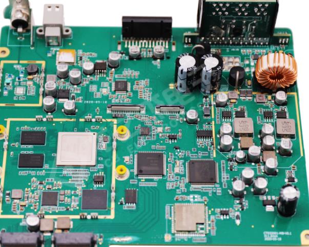
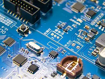
Function of Chip Capacitor on PCB
SMD capacitor is a kind of capacitance information. SMD capacitor is also known as multilayer (multilayer, laminated) chip ceramic capacitor, also known as SMD capacitor, chip capacitor. Chip capacitors have two types of pipes, one in inches and the other in millimeters. The SMD capacitor mainly has the following functions on the PCB.
1. Bypass
The bypass capacitor is an energy storage device that provides energy for local devices. It can make the output of the regulator uniform and reduce the load demand. Like small rechargeable batteries, bypass capacitors can charge and discharge equipment. To minimize impedance, bypass capacitors should be located as close as possible to the power and ground pins of the load device. This can prevent ground potential rise and noise caused by excessive input value. The ground potential is the voltage drop at the ground connection when a large current fault passes.
2. Decoupling
Decoupling is also calLED decoupling. From the perspective of circuit, it can always be divided into drive source and drive load. If the load capacitance is relatively large, the drive circuit must charge and discharge the capacitance to complete the signal jump. When the rising edge is relatively steep, the current is relatively large, and this driving current will absorb larger power supply current. Inductance and resistance (especially the inductance on the chip pin will rebound). Compared with the normal condition, the current is actually a kind of noise, which will affect the normal operation of the previous stage. This is called "coupling".
The decoupling capacitor acts as a "battery" to meet the change of the drive circuit current and avoid mutual coupling interference.
The combination of bypass capacitors and decoupling capacitors will be easier to understand. The bypass capacitor is actually decoupled, but the bypass capacitor usually refers to the high-frequency bypass, which is a low impedance leakage prevention method to improve high-frequency switching noise. The high frequency bypass capacitor is usually relatively small, usually 0.1mF, 0.01mF, etc. according to the resonant frequency; The capacity of decoupling capacitor is usually large, which may be 10mF or more, depending on the distribution parameters in the circuit and the change of driving current. Bypass is to filter the interference in the input signal, and decoupling is to filter the interference in the output signal to prevent the interference signal from returning to the power supply. This should be their essential difference.
3. Screening program
Theoretically (that is, the capacitor is assumed to be a pure capacitor), the greater the capacitance, the smaller the impedance and the higher the passing frequency. However, in fact, most capacitors above 1mF are electrolytic capacitors with large inductance components. In this case, when the frequency is high, the impedance will increase. SometiMES you will see a large electrolytic capacitor and a small capacitor in parallel. At this time, the large capacitor is connected to the low frequency and the small capacitor is connected to the high frequency. The function of capacitor is to transfer high impedance and low impedance, and transfer high frequency to block low frequency. The larger the capacitance, the easier it is to pass through low frequencies. It is specially used for filtering. Large capacitors (1000mF) filter low frequencies, and small capacitors (20pF) filter high frequencies. Some people use the filter capacitor as a "pond". Since the voltage at both ends of the capacitor will not change suddenly, it can be seen that the higher the signal frequency, the greater the attenuation. It can be said that the capacitor is like a pond, which will not change the water volume because of adding or evaporating a few drops of water. It converts voltage changes into current changes. The higher the frequency, the greater the peak current, thus buffering the voltage. Filtering is a process of charging and discharging.
4. Energy storage
The energy storage capacitor collects the charge through the rectifier, and transmits the stored energy to the output of the power supply through the converter wire Aluminum electrolytic capacitors with a voltage rating of 40450VDC and a capacitance value of 220150 000mF (such as B43504 or B43505 of EPCOS) are more commonly used. According to different power requirements, PCB devices are sometimes used in series, in parallel, or in combination For power supply with power level more than 10KW, larger groove SPIral terminal capacitor is usually used

抖音二維碼

Q Q二維碼

微信二維碼
點(diǎn)擊
然后
聯(lián)系
然后
聯(lián)系
電話熱線
13410863085Q Q

微信

- 郵箱