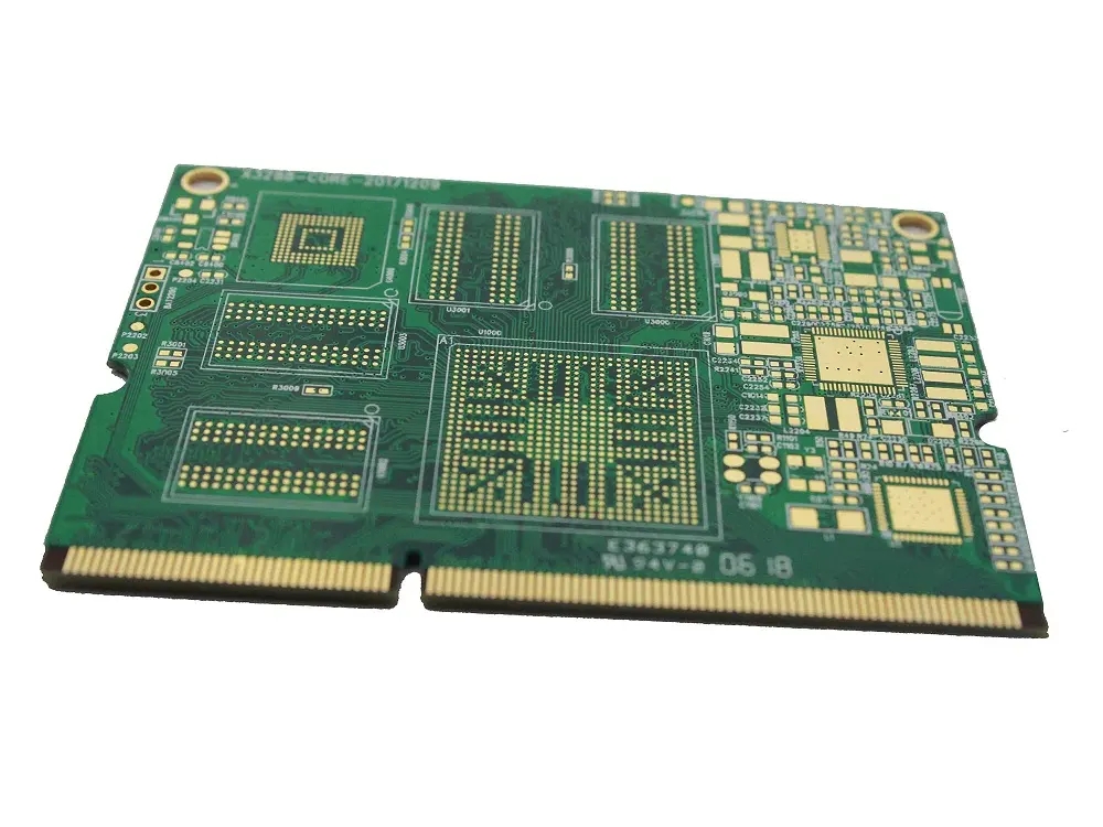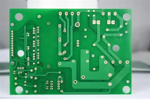
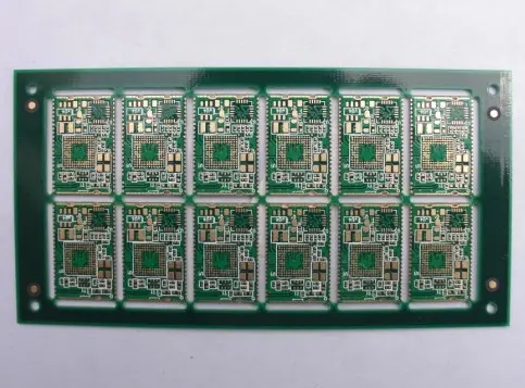
Decoupling Capacitor and Special DevICe Processing of Circuit Board Anti interference
Reasonable Setting of circuit board and Circuit Anti interference Processing of Decoupling Capacitors and Special Devices
The anti-interference design of printed circuit board is closely related to the specific circuit. The following discusses the anti-interference design measures of PCB from two aspects.
1. Reasonably set decoupling capacitor
High frequency decoupling capacitor with good performance can remove high frequency components up to 1GHz. CeramIC chip capacitors or multilayer ceramic capacitors have better high-frequency characteristics. The decoupling capacitor has two functions: on the one hand, it bypasses the high-frequency noise of the device. The typical decoupling capacitance in the digital circuit is 0.1uF, with 5nH distributed inductance. Its parallel resonance frequency is about 7MHz. It has good decoupling effect for noise below 10MHz, and has little effect on noise above 40MHz. The parallel resonance frequency of 1uF and 10uF capacitors is above 20MHz, and the effect of removing high-frequency noise is better. It is often advantageous to have a 1uF or 10uF high-frequency capacitor at the place where the power supply enters the printed board. Even battery powered systems need this capacitor. One charge discharge capacitor, or storage discharge capacitor, shall be added for every 10 or so integrated circuits. The capacitor size can be 10uF. It is better not to use electrolytic capacitor. The electrolytic capacitor is rolLED up by two layers of film. This rolled up structure behaves as an inductance at high frequencies. It is better to use a gallbladder capacitor or polycarbonate capacitor. The selection of decoupling capacitance value is not strict. It can be calculated as C=1/f, that is, 0.1uF for 10MHz. For the system composed of micro controller, it can be taken as 0.1~0.01 uF. The general configuration principle of decoupling capacitor is:
The power input terminal is connected with 10~100uF electrolytic capacitor. If possible, it is better to connect the cable above 100uF.
In principle, each integrated circuit chip should be equipped with a 0.01uF ceramic chip capacitor. If the gap between printed boards is insufficient, a 1-10uF tantalum capacitor should be arranged for every 4-8 chips.
For devices with weak anti noise ability and large power supply change during shutdown, such as RAM and ROM memory devices, decoupling capacitors should be directly connected between the power line and ground wire of the chip.
The capacitor lead shall not be too long, especially the high-frequency bypass capacitor shall not have lead.
2. Handling of special devices
When there are contactors, relays, buttons and other components in the printed circuit board, large spark discharge will occur when they are operated. RC circuit must be used to absorb the discharge current. Generally, R is 1~2K Ω, and C is 2.2~47uF.
CMOS has a high input impedance and is susceptible to induction, so the unused end should be grounded or connected to a positive power supply when in use.
Microcontroller with low external clock frequency can effectively reduce noise and improve the anti-interference ability of the system. In order to reduce the distortion in signal transmission, the delay time of signal transmission on the printed board shall not be greater than the nominal delay time of the device used.
Pay attention to the high-frequency characteristics of printed wire boards and components. In the case of high frequency, the lead, via, resistance, capacitance, distributed inductance and capacitance of connectors on the printed circuit board cannot be ignored. The reflection of the resistance on the high-frequency signal will play a role in the distributed capacitance of the lead. When the lead length is greater than 1/20 of the corresponding wavelength of the noise frequency, the antenna effect will be generated, and the noise will be transmitted outward through the lead. PCB manufacturers, PCB designers and PCBA manufacturers will explain how to deal with decoupling capacitors and special devices for anti-interference of PCB circuits.
然后
聯系
電話熱線
13410863085Q Q

微信

- 郵箱


