鑫景福致力于滿足“快速服務,零缺陷,輔助研發”PCBA訂購單需求。


行業新聞

Transmission Line Effect in High Speed PCB Design
Due to the transmission line effect, high-speed process PCB design will lead to some signal integrity problems How to deal with it? Here are four points to share with you:
1. StrICtly control the length of key network cables
If high-speed transition edge exists in the design, the influence of transmission line on PCB must be considered. This problem is more serious in today's fast integrated circuit chips with very high clock frequency. There are some basic principles to solve this problem: if CMOS or TTL circuits are used for design, the working frequency is less than 10MHz, and the wiring length should not exceed 7 inches. The operating frequency is 50MHz, and the wiring length shall not exceed 1.5 inches. If the operating frequency reaches or exceeds 75MHz, the wiring length shall be within 1 inch. The wiring length of the GaAs wafer shall be 0.3 inches. If this standard is exceeded, there is a problem with the transmission line.
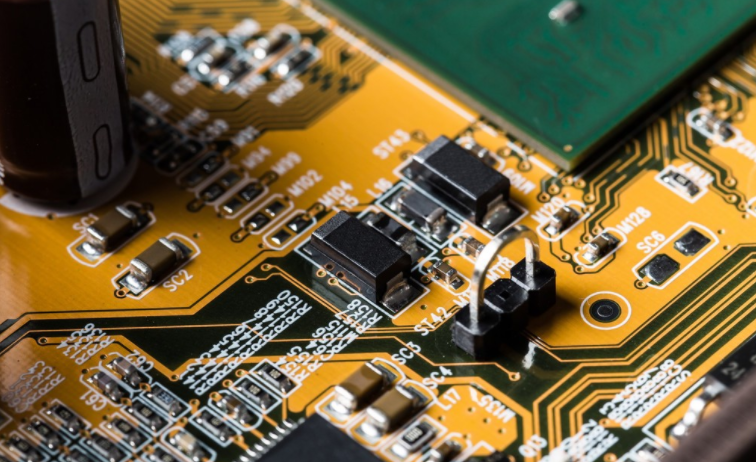
PCB board

2. Reasonable planning of trace topology
Another way to solve the impact of transmission lines is to choose the correct routing path and terminal topology. Routing topology refers to the routing sequence and structure of network cables. When using high-speed logic devices, unless the track branch length is kept short, signals with rapidly changing edges will be distorted by the branch track on the signal trunk track. Under normal circumstances, PCB wiring uses two basic topologies, namely daisy chain wiring and star distribution. For daisy chain wiring, the wiring starts from the driver and then arrives at the receiver. If the series resistor is used to change the signal characteristics, the series resistor shall be close to the drive terminal. In terms of high harmonic interference of control wiring, daisy chain wiring is very effective. However, the routing rate of this routing method is not easy to 100% route. In the actual design, we make the branch length in the daisy chain wiring as short as possible, and the safety length value should be: star topology can effectively avoid the clock signal non synchronization problem, but it is manually completed on the high-density pcb board. Wiring is very difficult. The use of an automatic external connector is a way to achieve star wiring. Terminating resistors are required on each branch. The value of the terminating resistor should match the characteristic impedance of the connection. This can be calculated manually or by CAD tools to calculate the characteristic impedance value and terminal matching resistance value. SIMple terminating resistors were used in the above two examples, but more complex matching terminals can actually be used. One option is RC match termination. RC matching terminal can reduce power consumption, but it can only be used when signal operation is relatively stable. This method is suitable for matching clock line signals. The disadvantage is that the capacitance in the RC matching terminal will affect the shape and speed of the signal. The series resistance matching terminal will not generate additional power consumption, but will reduce the signal transmission rate. This method is applied to bus drive circuit, in which time delay has little effect. The advantage of series resistance matching terminal is that it can reduce the number of components used and the wiring density on the circuit board. One method is to separate the matching terminal, where the matching part needs to be placed near the receiving end. The advantage is that it will not reduce the signal and avoid noise. Usually used for TTL input signals (ACT, HCT, FAST). In addition, the package type and installation type of the terminal matching resistor must be considered. In general, the inductance of SMD surface mount resistors is lower than that of through-hole components, and this smd package component becoMES. If you choose a common series resistor, there are also two installation methods: vertical and horizontal. In the vertical installation method, one of the mounting pins of the resistor is very short, which can reduce the thermal resistance between the resistor and the circuit board, and make the heat of the resistor more easily distributed to the air. However, a longer vertical installation will add inductance to the resistor. Due to the low installation, the level installation has a low inductance. However, the overheat resistor will drift. In the worst case, the resistor will become an open circuit, leading to the failure of PCB trace terminal matching and becoming a potential fault factor.
3. Methods for suppressing electromagnetic interference
A good solution to the signal integrity problem will improve the electromagnetic compatibility (EMC) of PCB. It is very important to ensure that the PCB board has a good grounding. Using a signal layer with a ground plane is a very effective method for complex design. In addition, making the signal density of the outer layer of the circuit board is also a good way to reduce electromagnetic radiation. This method can be realized by using the "surface layer" technology to manufacture PCB boards. The surface area layer is realized by adding a combination of thin insulation layer and micro through-hole, which is used to penetrate these layers on the common process PCB. Resistors and capacitors can be buried under the surface layer, and the trace density of each tissue area will almost double, which can reduce the volume of PCB. The reduction of PCB area has a great impact on the topology of the trace, which means that the current loop is reduced, the branch trace length is reduced, and the electromagnetic radiation is approximately proportional to the area of the current loop; At the same time, the SMAll volume characteristics mean that high-density lead can be used to package devices, which in turn reduces wire length, reduces current loops, and improves electromagnetic compatibility.
4. Other technologies available
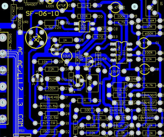
To reduce the transient overshoot of the voltage on the power supply of the integrated circuit chip, a decoupling capacitor should be added to the integrated circuit chip This effectively eliminates the impact of power failure and reduces the radiation of power circuit on the printed circuit board When the decoupling capacitor is directly connected to the power leg of the integrated circuit instead of the power plane, the effect of its fault smoothing is: This is why some devices have decoupling capacitors on their sockets, while others require decoupling capacitors to be sufficiently close to the device Any high-speed and high-power equipment shall be placed together as far as possible to reduce transient overshoot of power supply voltage Without a powered aircraft, the long power trace can create a loop between the signal and the loop, becoming a radiation source and a sensitive circuit The case where the track forms a loop that does not cross the same network cable or other tracks is calLED open loop If the loop crosses other traces of the same network line, a closed loop is formed Antenna effects are created in both cases (wire antennas and loop antennas). The antenna generates EMI radiation to the outside, and it is also a sensitive circuit A closed loop is necessary because its radiation is approximately proportional to the area of the closed loop PCB


抖音二維碼

Q Q二維碼

微信二維碼
點擊
然后
聯系
然后
聯系
電話熱線
13410863085Q Q

微信

- 郵箱